Up to this point in the pathway we’ve been comfortably abstract: addresses, subnets, routing decisions. Below all of that is the part of networking that’s genuinely physical — copper twisted pairs, glass strands, radio waves, and the connectors and transceivers that hold them together. The fancy phrase for it is the physical layer. The practical version: what’s actually carrying your bits.
This is lesson 6 of Networking from Scratch. You don’t need to memorise every cable rating to do useful network work, but you do need to know the trade-offs — pick the wrong cable category and you’ll cap your throughput; pick the wrong fiber type and your link won’t come up; pick the wrong Wi-Fi band and your office of fifty laptops will fight for airtime. This article gives you the working knowledge.
Copper Ethernet: the cabling almost everything ends in
The cable that comes out of every desktop PC, every IP phone, every printer, and every Wi-Fi access point is some flavour of twisted pair copper. Eight conductors, four pairs, terminated in an RJ45 connector at each end. The pairs are twisted around each other to cancel out electromagnetic interference — that’s where the name comes from.
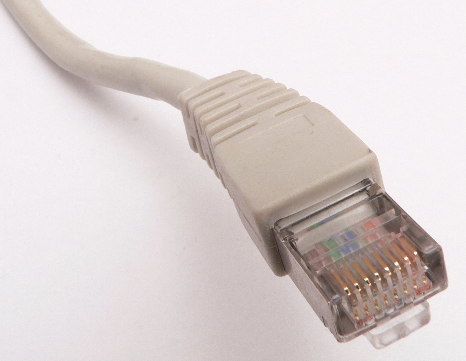
The cable comes in categories that define how fast and how far it can carry signal:
| Category | Speed | Distance | Where you’ll see it |
|---|---|---|---|
| Cat 5e | 1 Gbps | 100 m | The minimum that should ever be installed today. Older buildings still have it; new ones go straight to Cat 6 or 6a. |
| Cat 6 | 1 Gbps at 100 m, 10 Gbps at 55 m | 100 m / 55 m | Common new install. Cheap, plentiful. |
| Cat 6a | 10 Gbps | 100 m | Enterprise standard for any new build that wants future-proof 10G to the desk or AP. |
| Cat 7 / 7a | 10 Gbps | 100 m | Heavily shielded. Rare in offices because Cat 6a is good enough; sometimes used in industrial settings with heavy EMI. |
| Cat 8 | 25 / 40 Gbps | 30 m | Data-centre top-of-rack to server, where short distances are fine. |
Two things to pay attention to: the distance limit is real, and it’s shorter than people think when they’re running cable through walls and ceilings (every coil and patch panel adds length); and the category at the slowest piece in the chain wins — if you connect a Cat 6a wall jack to a Cat 5 patch cord, your link is Cat 5.
T568A vs T568B (the wiring standards)
The two pinouts you’ll see in the wild for terminating an RJ45 are T568A and T568B. They differ only in whether the green and orange pairs are swapped. Either works as long as both ends of the cable use the same one. Mixing them at opposite ends gives you a crossover cable, which used to be needed to connect like-to-like devices (PC-to-PC, switch-to-switch); modern gear with Auto-MDI/MDIX figures it out automatically and you basically never need crossovers anymore. Pick one of T568A or T568B, write it on the wall, and use it consistently.
Power over Ethernet (PoE): copper that powers the device
Modern Ethernet can deliver electrical power along the same cable that carries data. That’s why Wi-Fi access points, IP phones, and a lot of cameras don’t need a separate power brick — the switch port supplies them. The flavours you’ll meet:
| Standard | Common name | Max power at the device | Use cases |
|---|---|---|---|
| 802.3af | PoE | ~12.95 W | VoIP phones, basic cameras, small APs. |
| 802.3at | PoE+ | ~25.5 W | Wi-Fi 5/6 APs, PTZ cameras, small video phones. |
| 802.3bt Type 3 | PoE++ / 4PPoE | ~51 W | Wi-Fi 6E APs, larger cameras, some thin clients. |
| 802.3bt Type 4 | PoE++ / Hi-PoE | ~71.3 W | Wi-Fi 7 APs, displays, small PCs, LED lighting. |
Two practical rules: each switch has a total PoE budget (often a fraction of the per-port theoretical maximum × the port count), and not every switch port is PoE. Read the spec sheet, count up the wattage your devices need, and don’t buy a switch with 24 PoE+ ports and a 200 W budget if you have 24 access points that each want 25 W.
Fiber: glass for distance and bandwidth
Copper hits a wall at 100 m for typical Ethernet rates. Fiber doesn’t. Anything between buildings, between floors of a tall building, or between data-centre racks at high speed is going to be fiber.
Two flavours:
- Single-mode fiber (SMF) — thin core (~9 microns), uses a single laser pulse, very long reach (10 km is easy, 80 km+ is doable with the right optics). Yellow jacket by convention. Used for inter-building, metro, long-haul.
- Multi-mode fiber (MMF) — thicker core (~50 microns), can carry multiple light modes simultaneously. Shorter reach (550 m at 10 G, less at higher speeds). Cheaper transceivers. Orange or aqua jacket by convention. Used inside a data centre or campus.
The two are not compatible. SMF transceivers don’t talk to MMF, and the cores are different sizes — you can’t even physically mate them with a coupler that works.
Connectors you’ll handle
| Connector | What it looks like | Used for |
|---|---|---|
| LC | Small square, latch on top, two ferrules side by side (Tx + Rx) | Modern dominant connector. Most enterprise and DC fiber. |
| SC | Larger square, push-pull | Older installs, some carrier gear. Still very common. |
| MPO / MTP | Wide rectangle, 12 (or 24) fibres in one ferrule | 40G/100G optics that need parallel fibres. High-density data-centre wiring. |
| ST | Bayonet twist-lock, single ferrule | Legacy. You’ll find it in older comms rooms. |
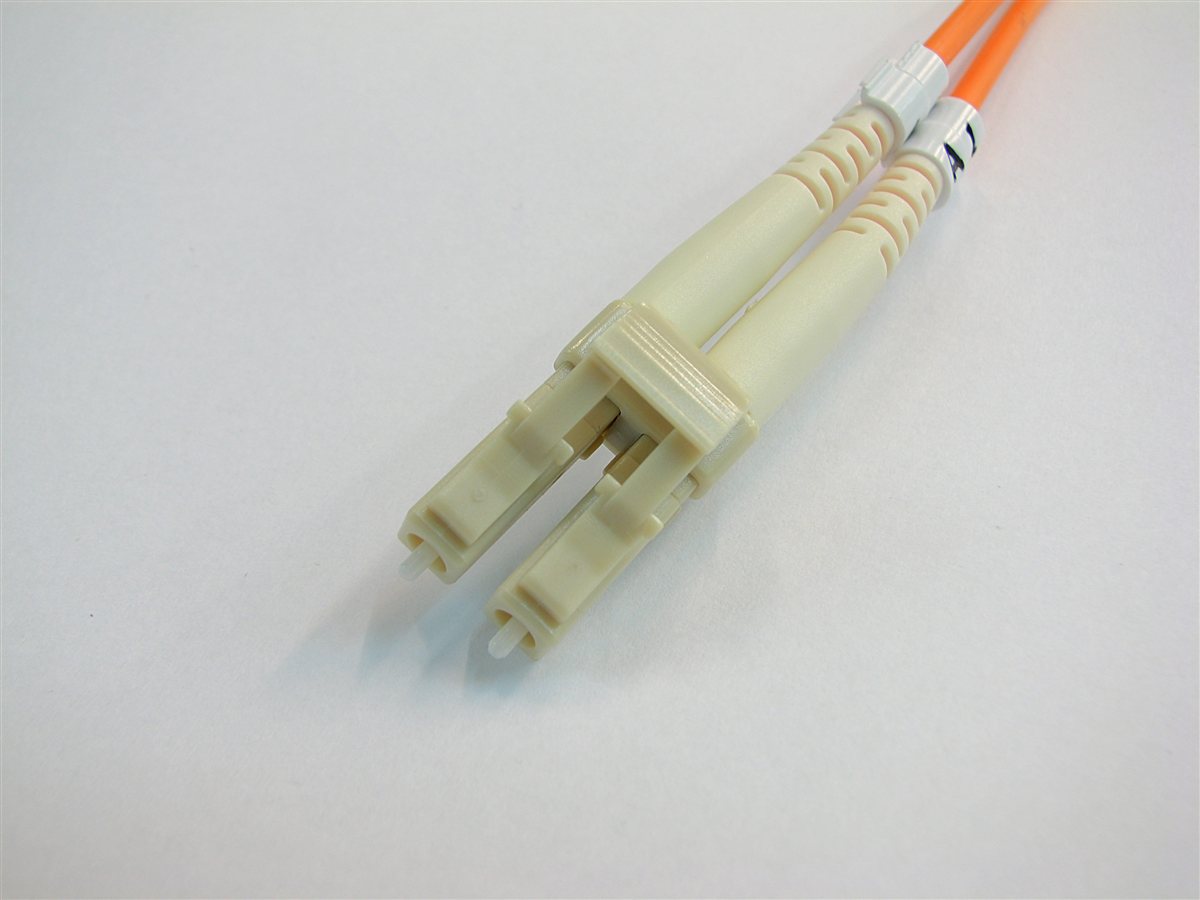
Transceivers (the “optics”)
The actual electronics that turn an electrical Ethernet signal into light come in hot-pluggable modules that slot into a switch or NIC port. The form factor names map roughly to speed:
| Form factor | Typical speed |
|---|---|
| SFP | 1 Gbps |
| SFP+ | 10 Gbps |
| SFP28 | 25 Gbps |
| QSFP+ | 40 Gbps (4 × 10 G lanes) |
| QSFP28 | 100 Gbps |
| QSFP-DD / OSFP | 400 / 800 Gbps |
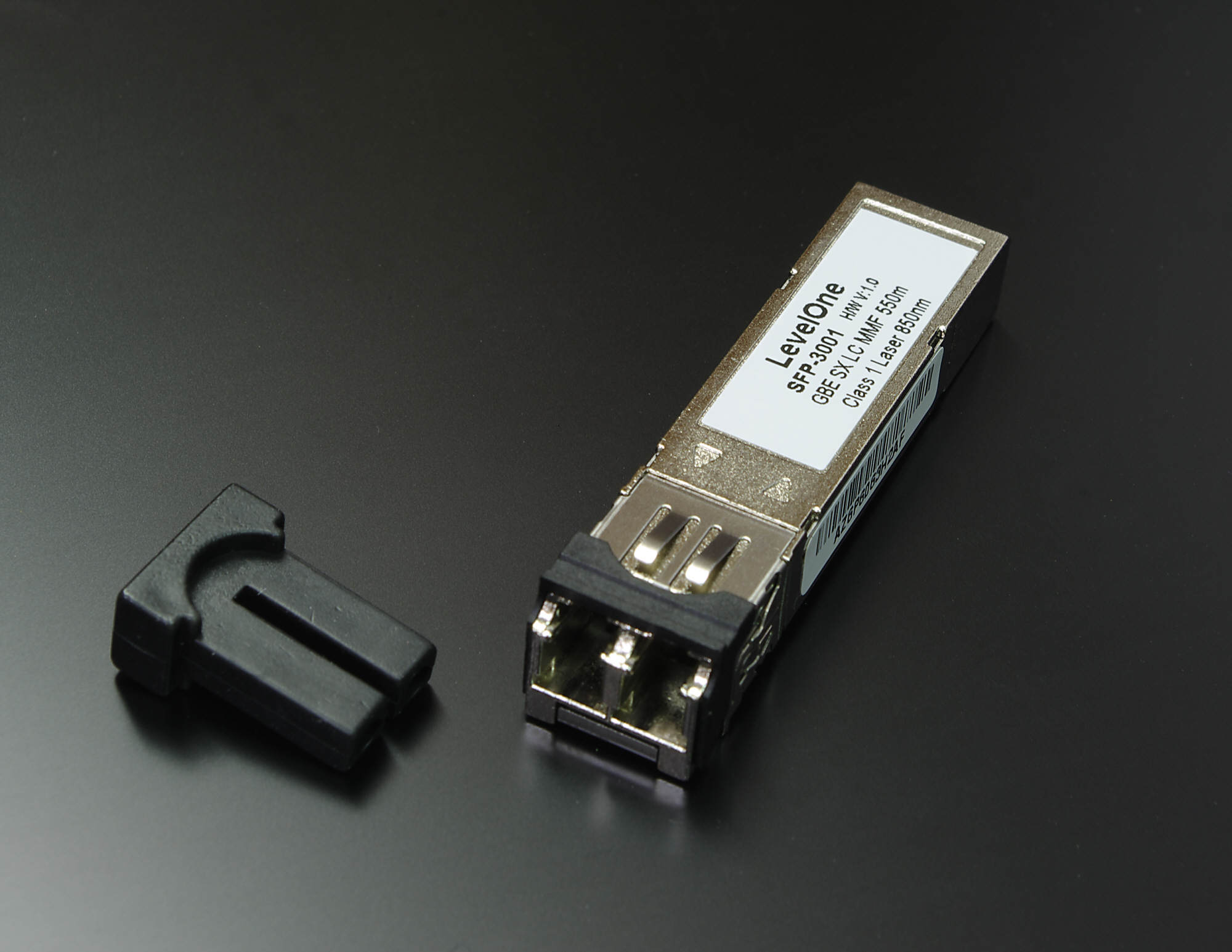
Each transceiver is built for a specific fiber type, distance, and wavelength. A “10G SR” module is short-reach over MMF; “10G LR” is long-reach over SMF. The transceiver and the fiber type have to match at both ends.
One ergonomic rule: if a link won’t come up and the cable’s good, swap the transceiver before you swap anything else. Optics fail more often than copper does and the symptoms look identical from the host side.
Wi-Fi: bits without wires
Wi-Fi is just Ethernet’s wireless sibling. Same frame format at the top, very different physical layer underneath. The key thing for an admin to understand is the spectrum — what frequencies Wi-Fi uses, how those frequencies divide into channels, and why some bands are nicer to live in than others.
| Band | Channels | Range / wall penetration | Reality |
|---|---|---|---|
| 2.4 GHz | 1, 6, 11 (the 3 non-overlapping ones) | Best | Loved by IoT and microwaves. Crowded. Avoid for serious laptops. |
| 5 GHz | ~25 non-overlapping channels (varies by region) | Worse than 2.4 | Currently the workhorse. Plenty of channels, less interference. |
| 6 GHz | ~59 non-overlapping channels (Wi-Fi 6E / 7) | Worst of the three | Lots of clean spectrum if your devices support it. The future. |
2.4 GHz is special because of one historical accident: only three of its channels (1, 6, 11) don’t overlap with each other, so a busy office can’t fit more than three non-interfering 2.4 GHz access points within earshot. Add Bluetooth, microwave ovens, baby monitors, and every smart bulb on the floor, and 2.4 is genuinely a swamp.
5 GHz is where laptops and phones live. More channels, more space, less interference. The trade-off is that 5 GHz waves don’t penetrate walls as well, so you need more access points to cover the same area.
6 GHz, available in Wi-Fi 6E and Wi-Fi 7, is enormous — over a thousand MHz of spectrum, with roughly 59 channels at 20 MHz width. The catch is short range, which actually turns out to be a feature: clients in different rooms don’t step on each other.
Wi-Fi standards (the friendly names)
| Marketing name | IEEE name | Bands | Practical max throughput |
|---|---|---|---|
| Wi-Fi 4 | 802.11n | 2.4 + 5 GHz | ~150–600 Mbps |
| Wi-Fi 5 | 802.11ac | 5 GHz only | ~1.7 Gbps |
| Wi-Fi 6 | 802.11ax | 2.4 + 5 GHz | ~2.4 Gbps |
| Wi-Fi 6E | 802.11ax + 6 GHz | 2.4 + 5 + 6 GHz | ~3 Gbps in good conditions |
| Wi-Fi 7 | 802.11be | 2.4 + 5 + 6 GHz | theoretical 30+ Gbps; real-world far less |
The Wi-Fi Alliance switched to friendly numbers (Wi-Fi 5, 6, 7) starting around 2018. Vendors still print both on the box.
Common physical-layer problems and how to recognise them
| Symptom | Likely physical-layer cause |
|---|---|
| Link light off entirely | Cable unplugged, broken, or wrong port. Try the cable in a known-good port. |
| Link comes up at 100 Mbps when it should be 1 Gbps | Cable is Cat 5 (not 5e), or one of the four pairs is broken — gigabit needs all four. Try a fresh patch cord. |
| Random packet loss only at high throughput | Cable too long, kinked, or stapled too tightly. Re-route or replace. |
| Wi-Fi works in some rooms, not others | 5 GHz coverage gap. Add an AP or check antenna placement. |
| Wi-Fi slow during business hours, fine after | Channel contention. Run a site survey, change channels, retire 2.4 GHz where possible. |
| Fiber link won’t come up | Wrong transceiver type, MMF connected to SMF optic, dirty connector, or polarity reversed (Tx-to-Tx instead of Tx-to-Rx). Swap the optic, then check the cable. |
| PoE device boots and immediately reboots | Switch port doesn’t supply enough power for the device’s class. Move to a higher-class PoE port or use a PoE injector. |
Physical-layer problems have a giveaway: they’re intermittent at higher speeds and clean at lower ones. If a link works at 100 Mbps but drops at 1 G, the cable is probably the issue. If a link works at 1 G but flaps at 10 G, the transceiver, fiber, or connector usually is.
What you can now answer
- What cable do I run for new installs? — Cat 6a if you can afford it, Cat 6 if not. Both give you 100 m at 1 G; Cat 6a gives you 100 m at 10 G.
- What does PoE class mean? — The maximum power the switch will deliver, divided into named tiers. Match the class to your device’s draw.
- Which fiber for which job? — SMF for distance, MMF for inside a building. They’re not interchangeable.
- Why does my Wi-Fi feel slow on Tuesdays? — Probably the 2.4 GHz band, possibly co-channel contention. Move clients to 5 or 6 GHz where you can.
- Where do I start when a link won’t come up? — Cable, then transceiver, then port, then far end. Cheap things first.
What’s next
You now have a full top-to-bottom picture: physical layer (this article), L2 forwarding (lesson 5), L3 routing (lesson 5 again), addressing (lessons 2 and 3), and how a host bootstraps onto a network (lesson 4). The next lesson goes back up the stack to look at TCP, UDP, and QUIC — the transport protocols that ride on top of IP, and how to pick the right one when you’re building or troubleshooting an application.