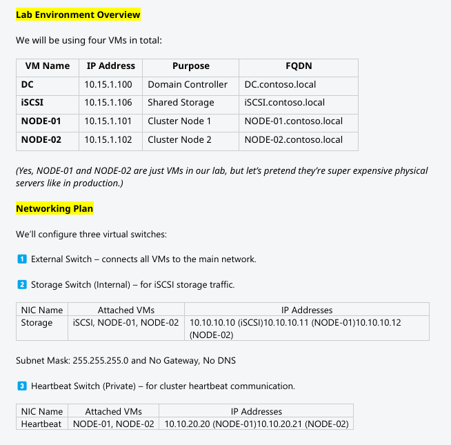
VMs are built. Now the network plumbing the cluster needs: three vSwitches (External, Storage, Heartbeat), attached to the right VMs with the right IPs, all ping-tested. Skip the ping matrix and three weeks from now you’ll be debugging a failover that “mysteriously” takes 90 seconds because heartbeat packets are being dropped on a misconfigured NIC.
Hyper-V vSwitch types — pick the right one per role
| Type | Binds to | Use for |
|---|---|---|
| External | Physical NIC + host + VMs | Public/Domain network — needs to reach the LAN |
| Internal | Host + VMs (no physical NIC) | Storage — isolated from physical LAN, host can manage |
| Private | VMs only (no host, no NIC) | Heartbeat — truly isolated cluster traffic |
Pick wrong and you’ve either exposed storage to the wrong network (External instead of Internal) or denied yourself host-side troubleshooting (Private when Internal would help).
Step 1 — verify the existing External vSwitch
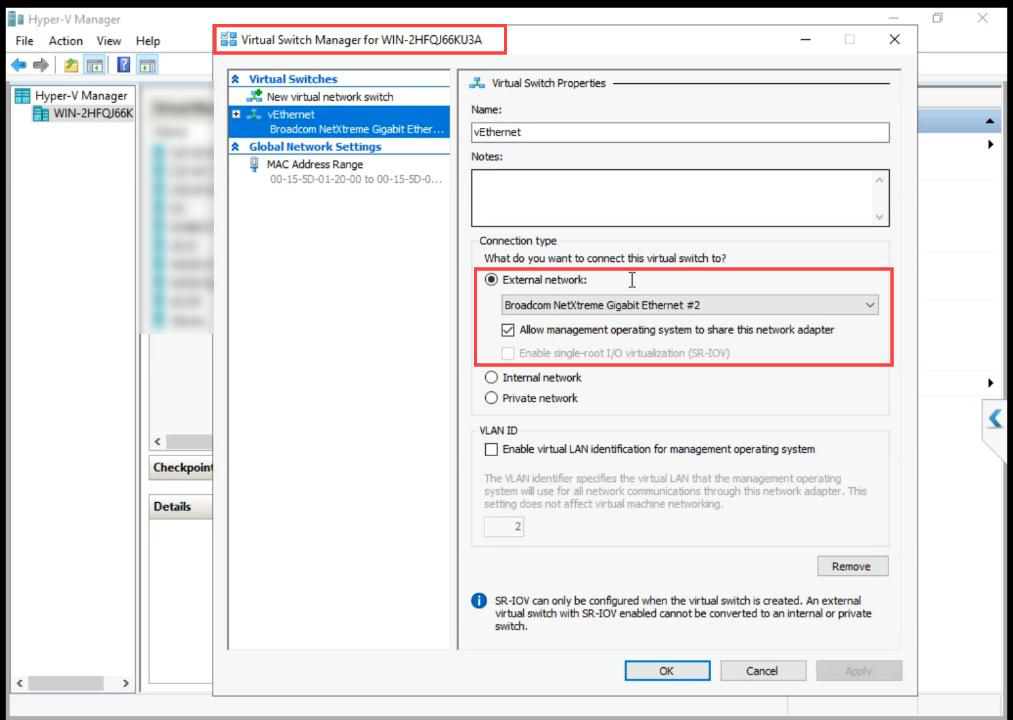
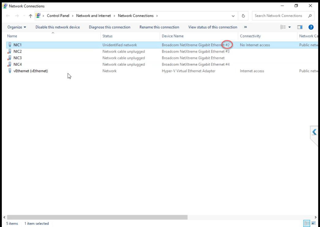
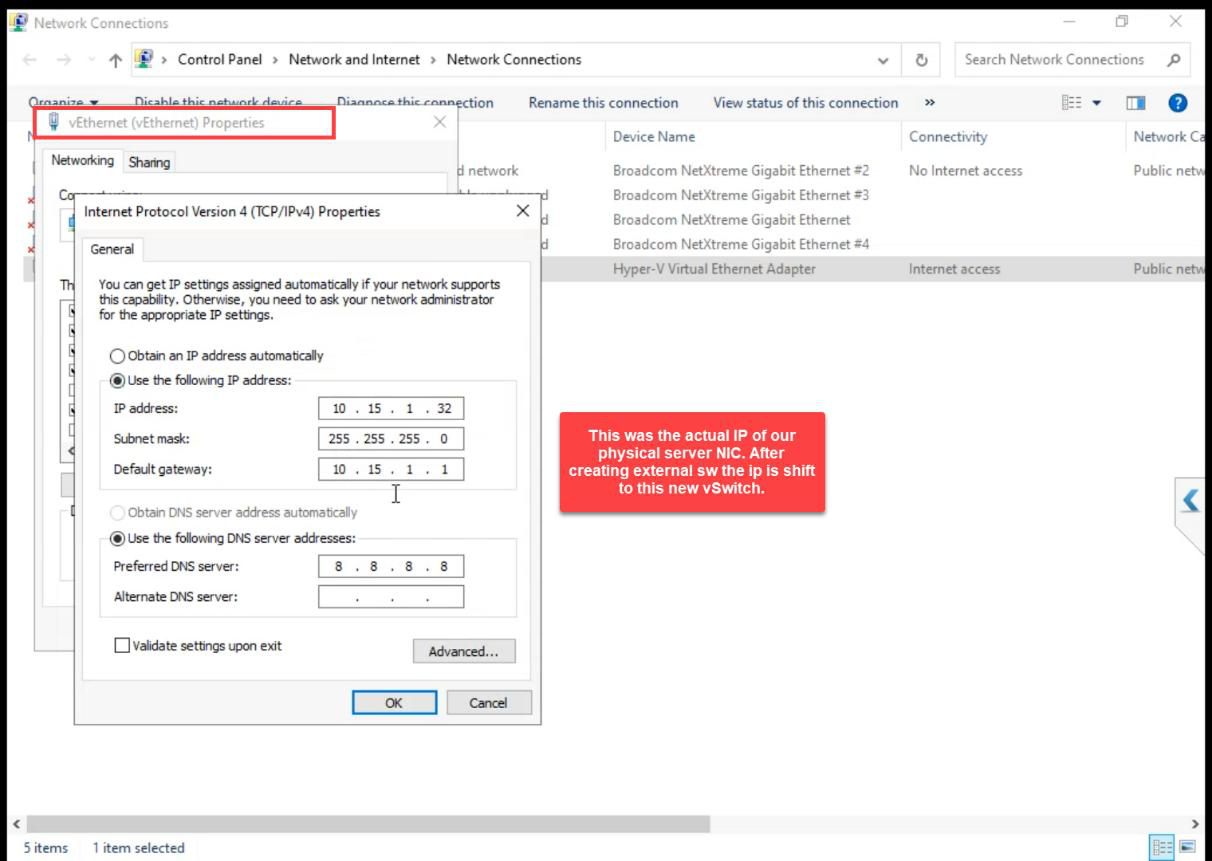
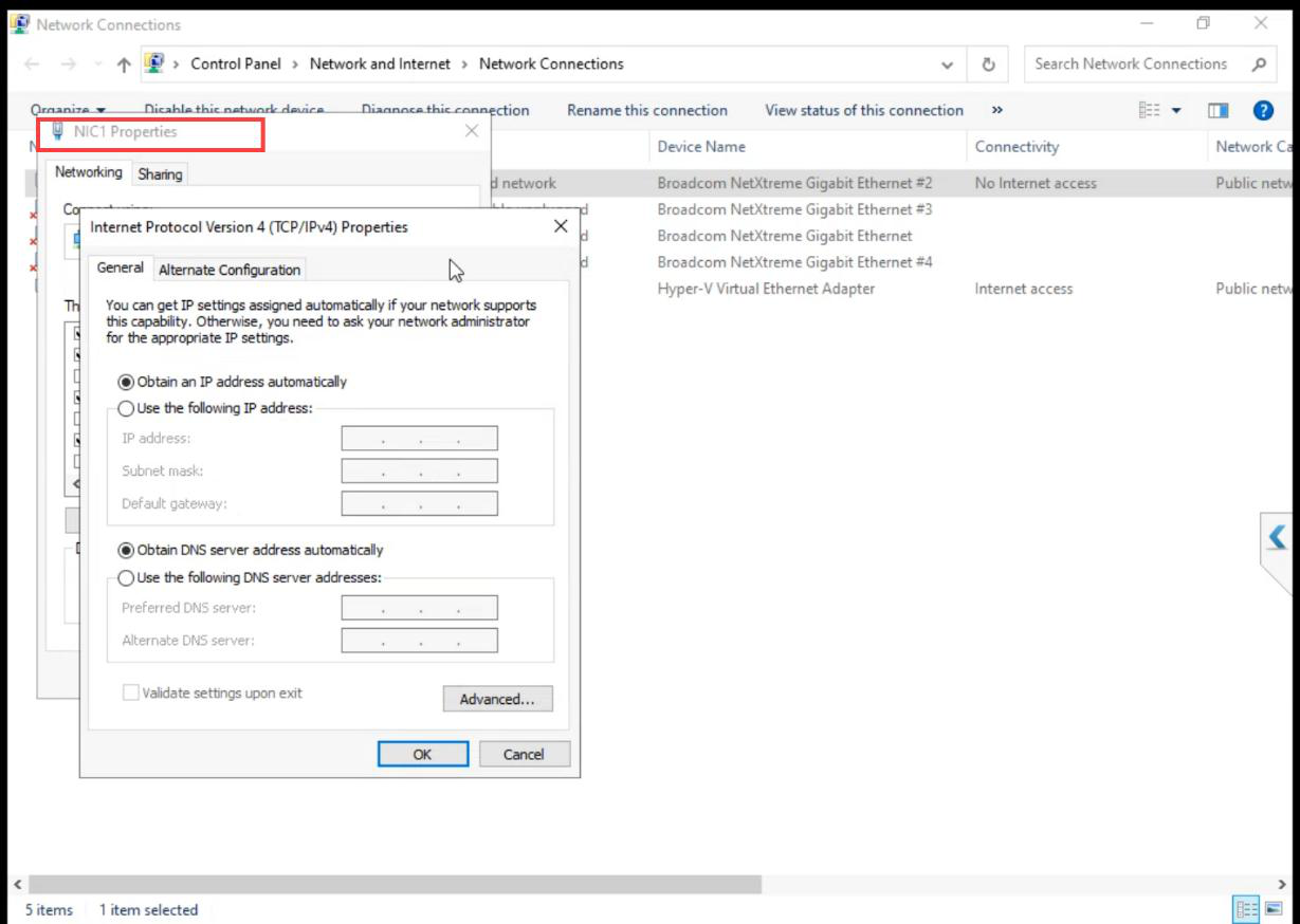
The External vSwitch was created when you set up Hyper-V originally. Verify Allow management OS to share this network adapter is ticked. Without it, the host loses network access when Hyper-V takes the NIC.
Step 2 — create the Storage vSwitch (Internal)
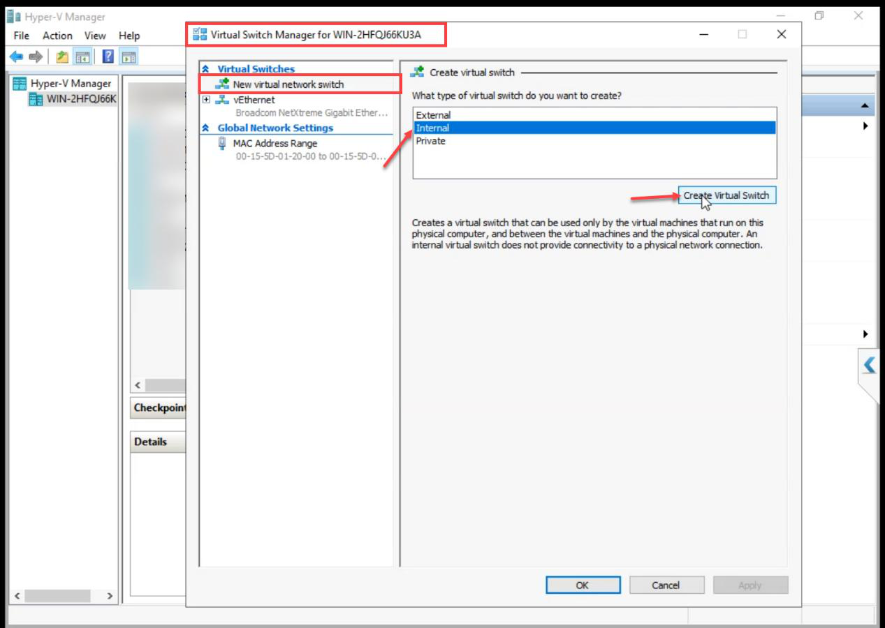
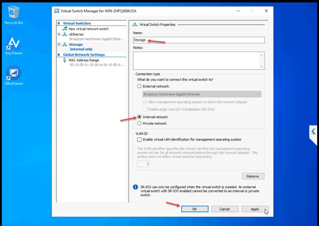
Storage. Type: Internal. OK.Name: Storage. Type: Internal. OK.
Internal means the host can also see this network if needed for troubleshooting, but no physical NIC is bound — storage traffic stays on the host.
Step 3 — create the Heartbeat vSwitch (Private)
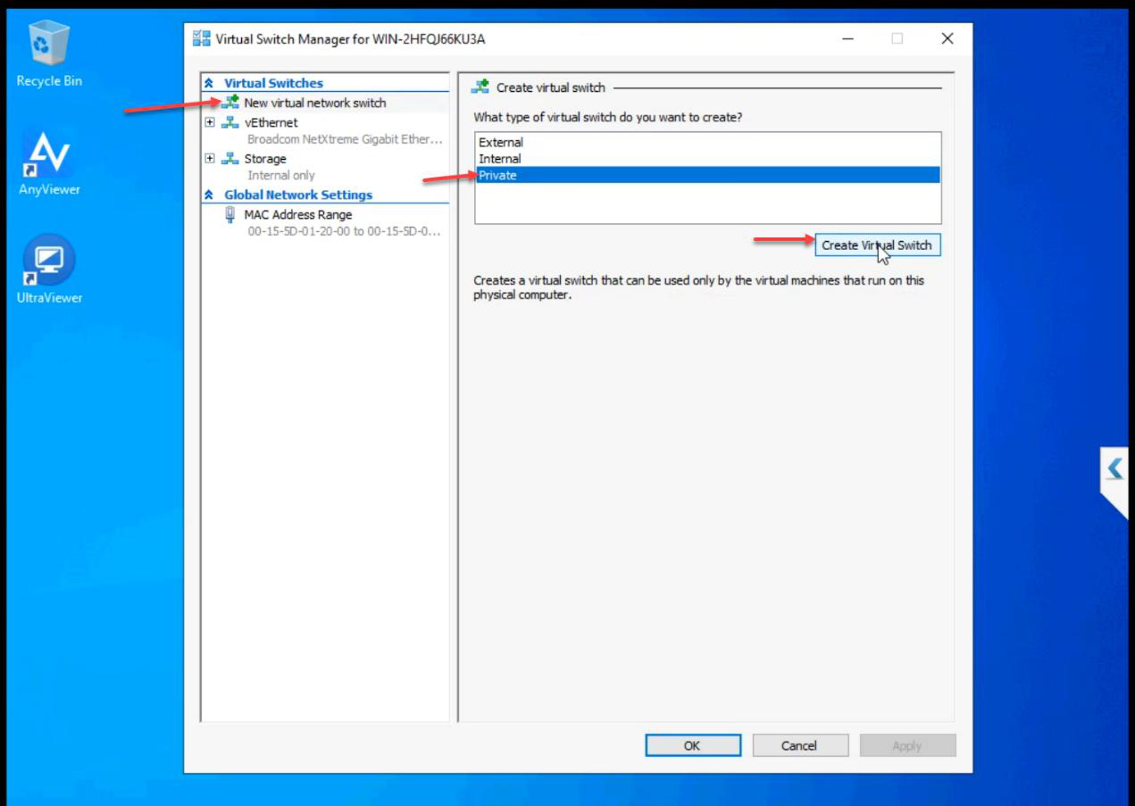
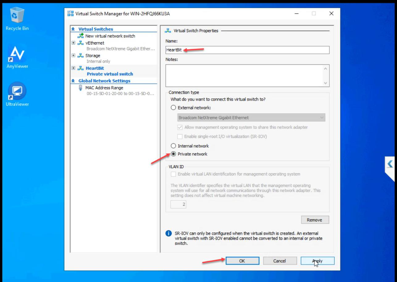
Heartbeat. Type: Private. OK.Name: Heartbeat. Type: Private. OK.
Private means VMs only — not even the host attaches. True isolation. Heartbeat traffic NEVER leaves the cluster nodes.
Step 4 — attach vSwitches to VMs
iSCSI VM (Storage only, no Heartbeat)
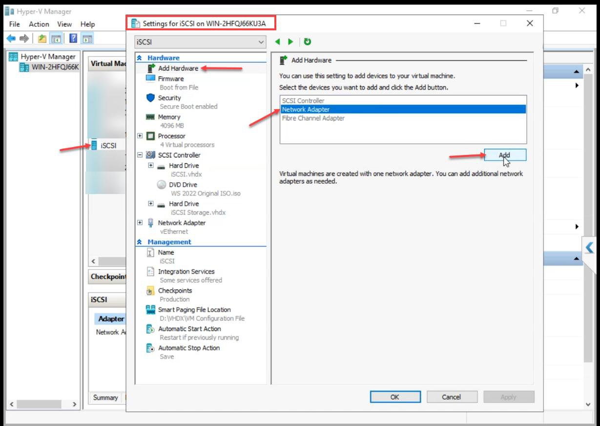
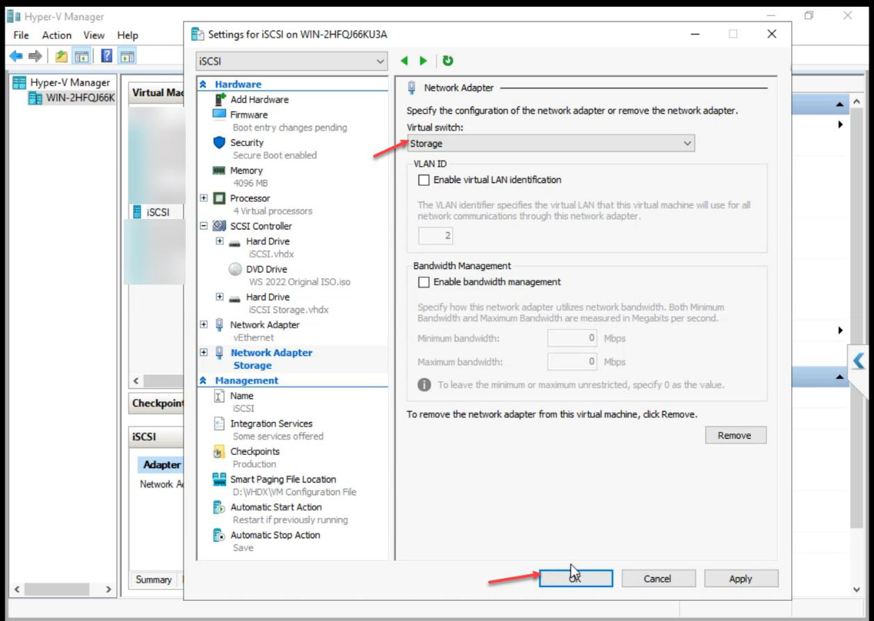
Add Hardware > Network Adapter > Storage vSwitch.
Critical: the iSCSI VM does NOT get the Heartbeat vSwitch. The SAN doesn’t vote in cluster quorum — attaching it to Heartbeat would put a non-voting device into the cluster’s liveness conversation.
NODE-01 (all three switches)
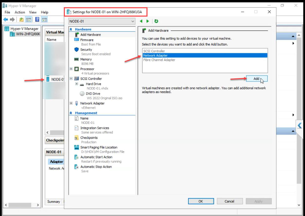
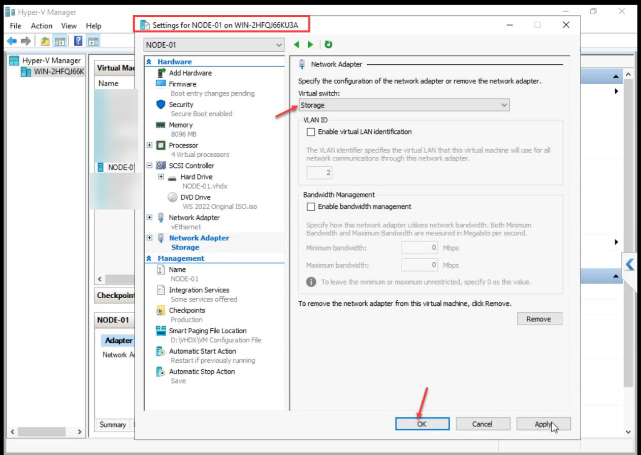
Add Network Adapter > Storage.
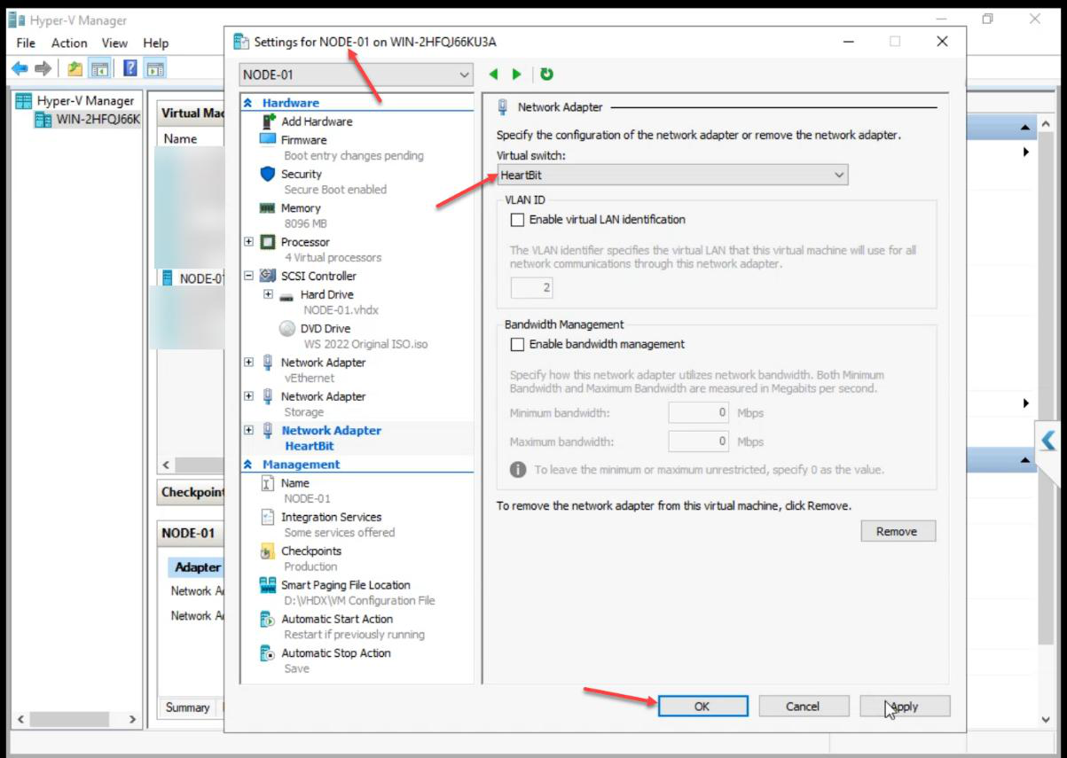
Add another Network Adapter > Heartbeat. NODE-01 ends up with 3 adapters (Public from create + Storage + Heartbeat).
NODE-02 (all three switches)
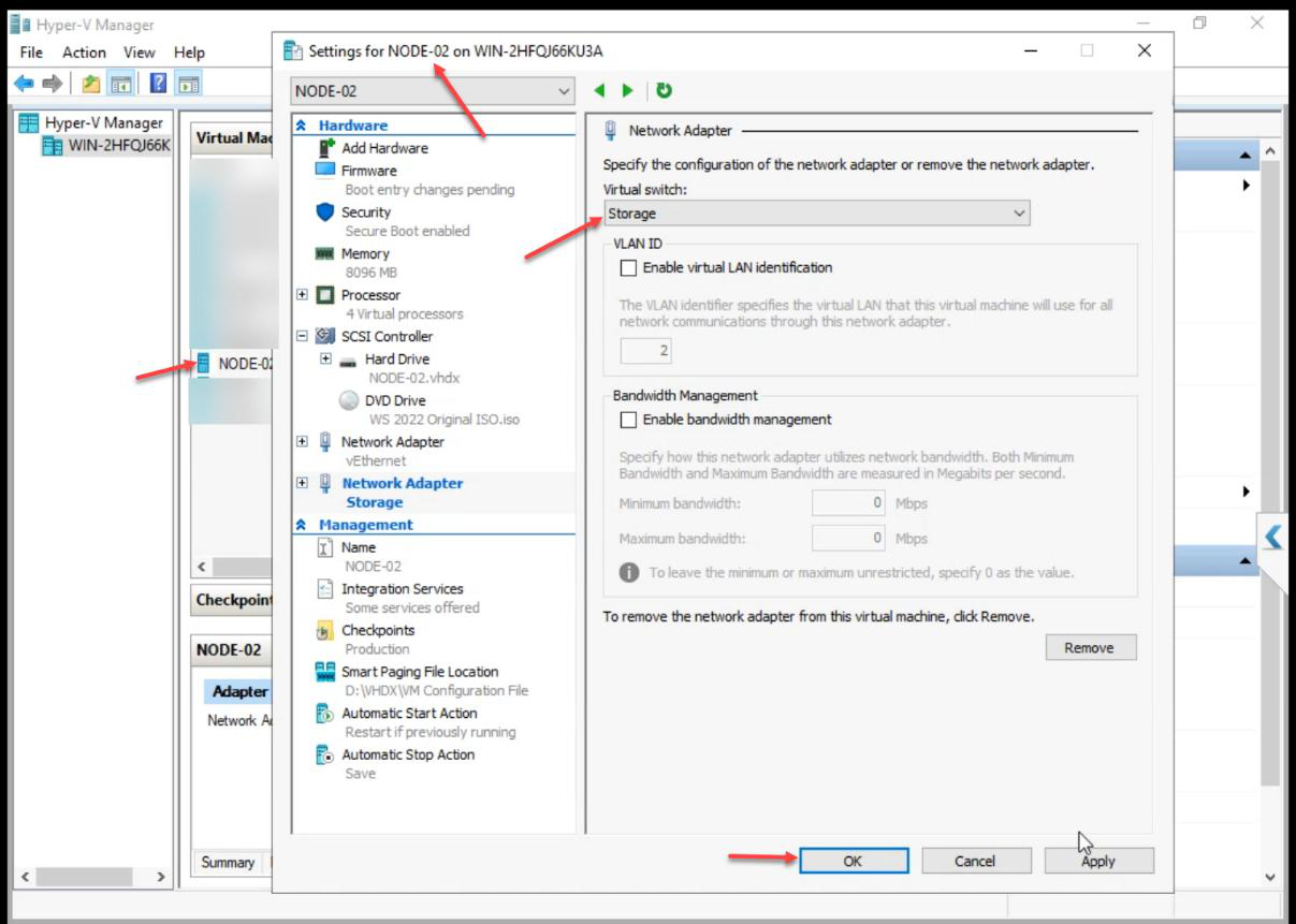
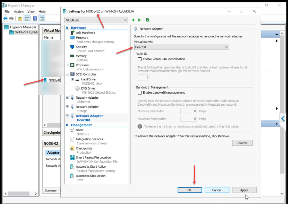
Same as NODE-01: Storage adapter + Heartbeat adapter.
Step 5 — verify VM adapter inventory
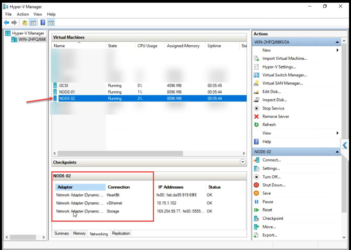
NODE-01 and NODE-02: 3 adapters each.
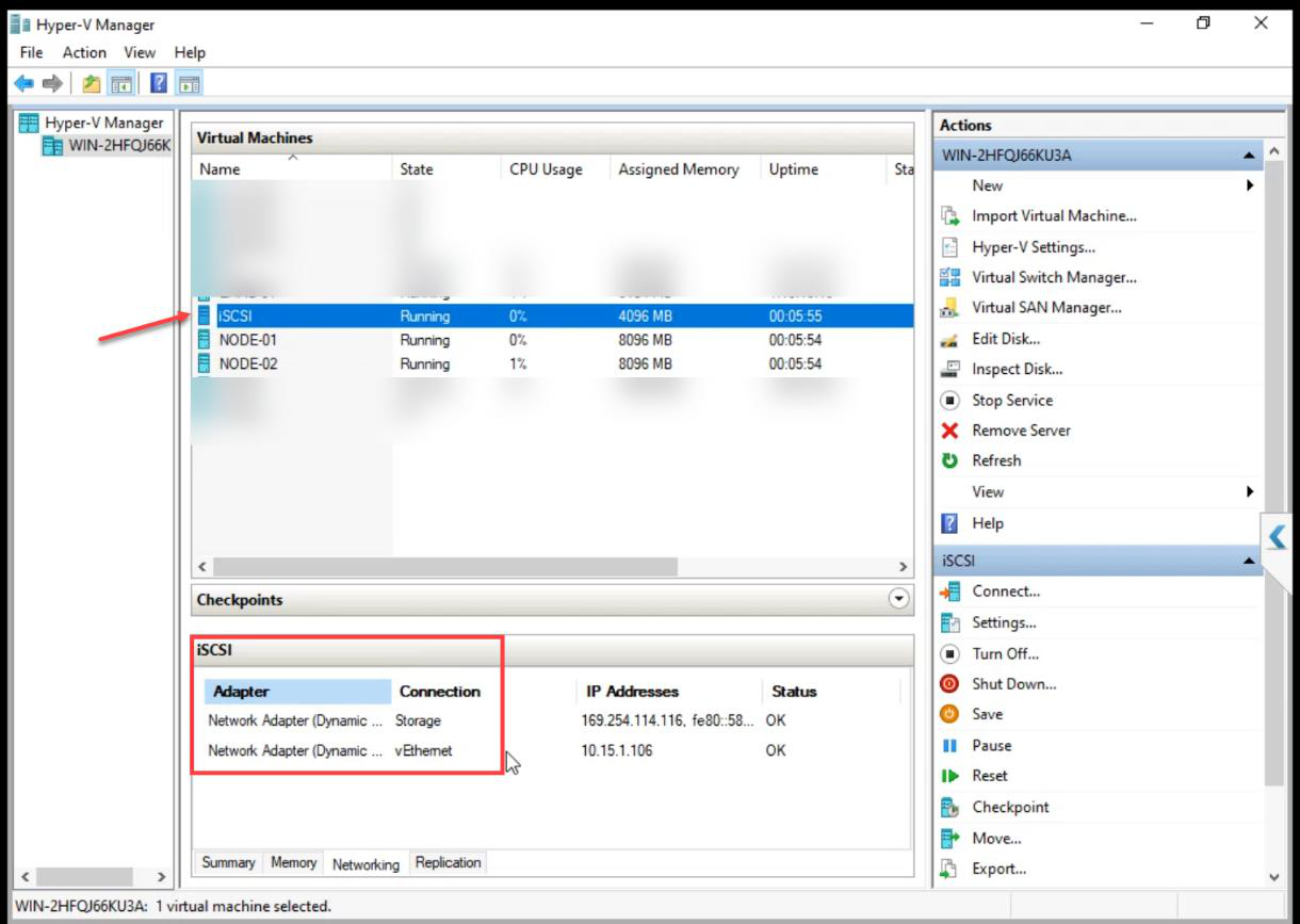
iSCSI VM: 2 adapters only (no Heartbeat).
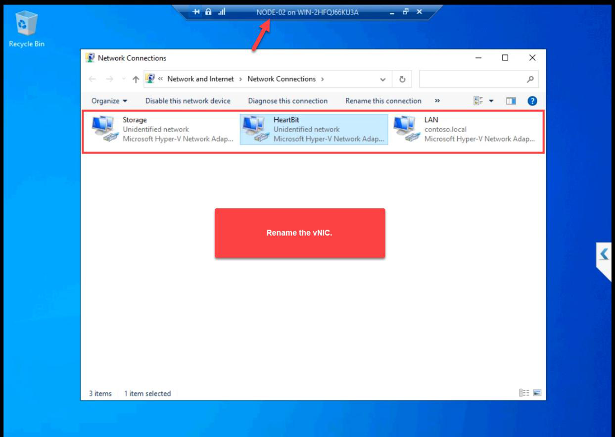
Step 6 — rename NICs in guest OS + assign IPs
Default Windows names are Ethernet, Ethernet 2, Ethernet 3. Useless for cluster validation reports and PowerShell. Rename now — saves 03:00 troubleshooting later.
iSCSI VM
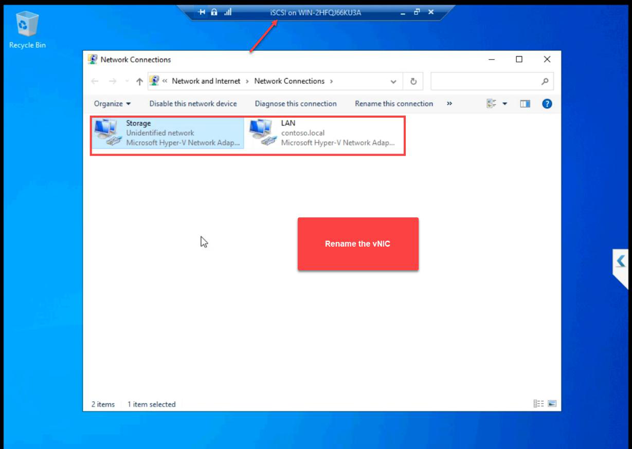
ncpa.cpl. Rename the two NICs to Public and Storage.Open ncpa.cpl. Rename to Public and Storage.

10.10.10.10. Subnet 255.255.255.0. No gateway, no DNS. Private subnet.Storage NIC: 10.10.10.10/24. No default gateway, no DNS. Private subnet doesn’t route off the host.
NODE-01
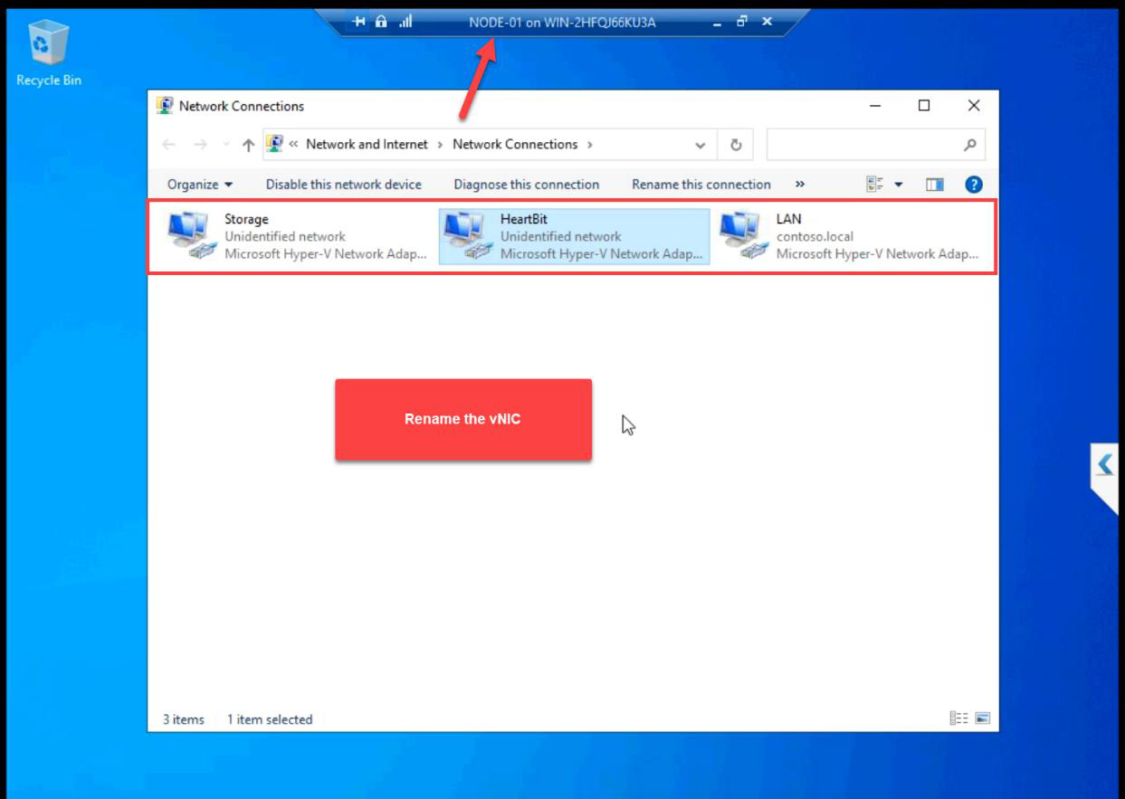
Public, Storage, Heartbeat.Three NICs renamed.

10.10.10.11/24. No GW, no DNS.Storage: 10.10.10.11/24.
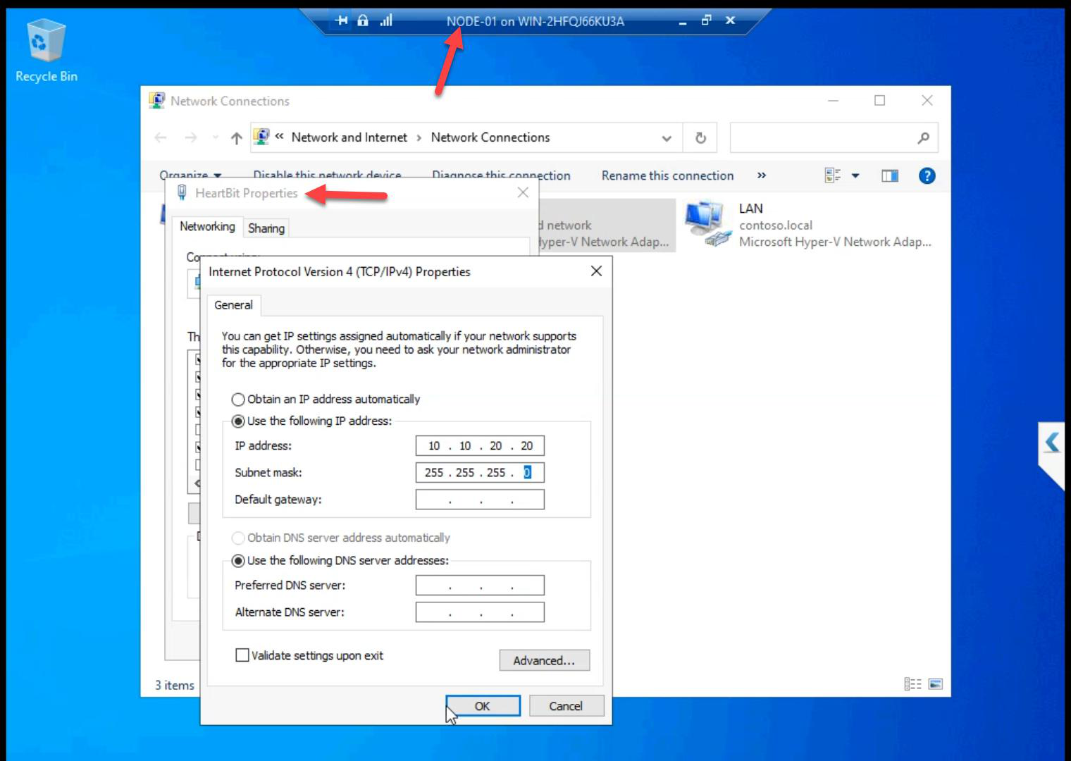
10.10.20.20/24.Heartbeat: 10.10.20.20/24.
NODE-02
Three NICs renamed.

10.10.10.12/24.Storage: 10.10.10.12/24.
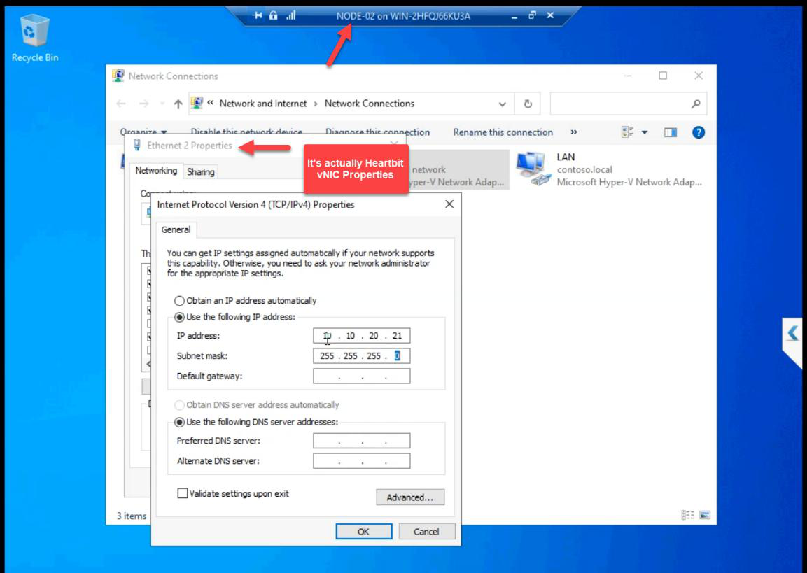
10.10.20.21/24.Heartbeat: 10.10.20.21/24.
Step 7 — ping matrix (do every cell)
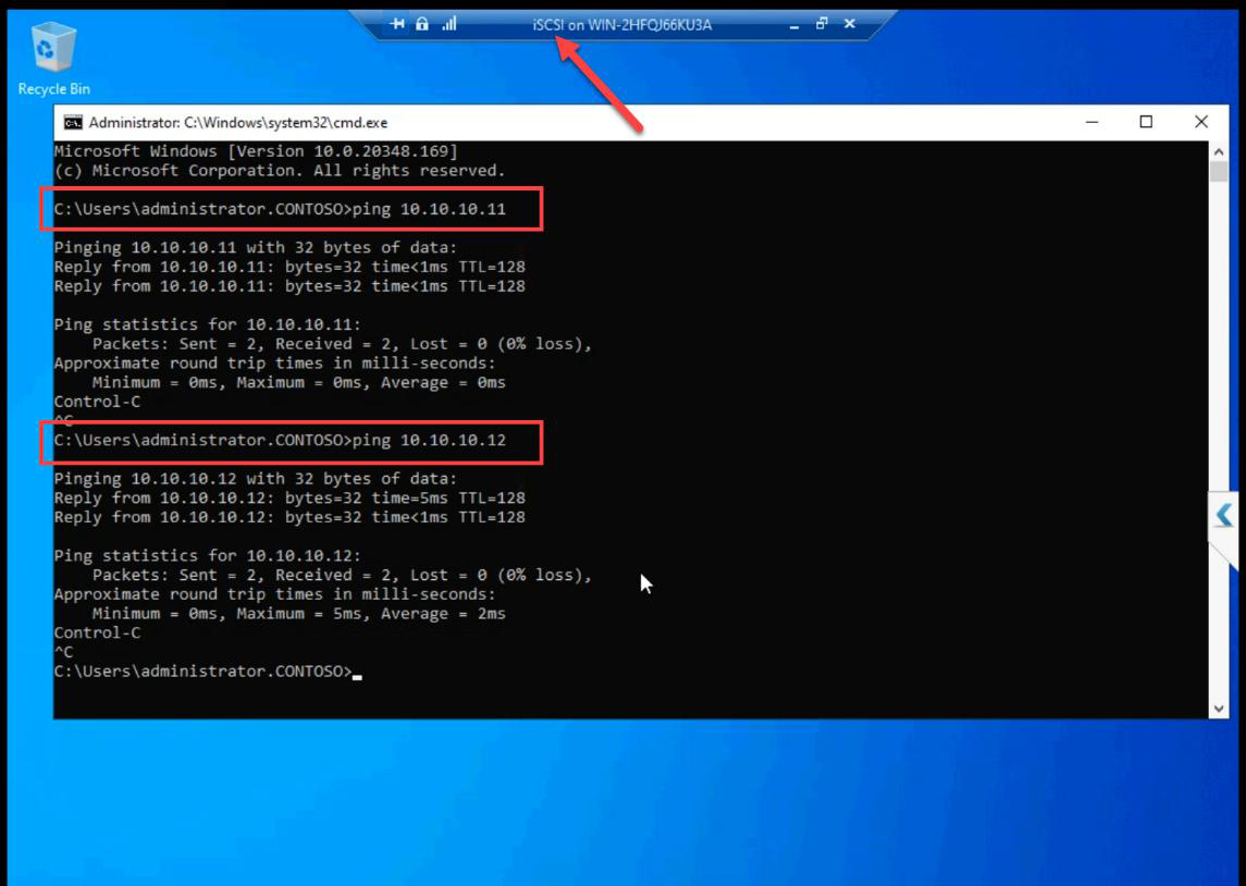
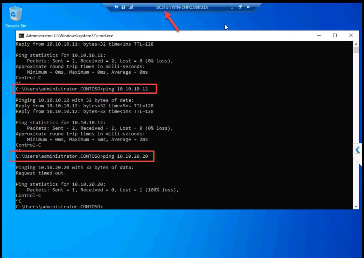
From iSCSI VM: ping NODE-01 storage (10.10.10.11), ping NODE-02 storage (10.10.10.12). Both succeed.
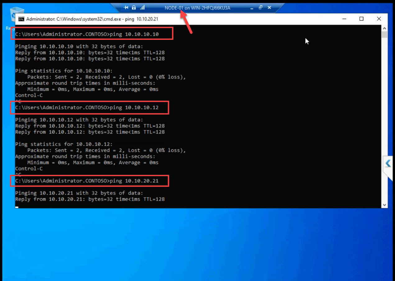
From NODE-01: ping iSCSI (10.10.10.10), ping NODE-02 (10.10.10.12) on storage; ping NODE-02 (10.10.20.21) on heartbeat. All succeed.
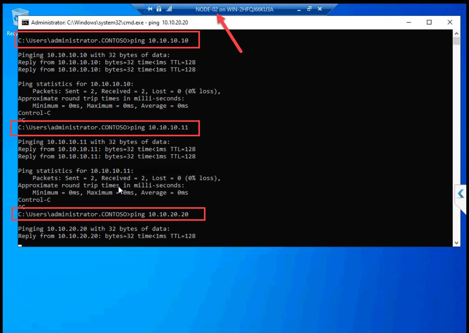
From NODE-02: ping iSCSI + NODE-01 on storage; ping NODE-01 on heartbeat. All succeed.
Final layout matches the Part 1 architecture table. Networks are clean. Cluster validation will pass.
Things that bite people in this part
Forgot “Allow management OS to share”
If you uncheck this when creating the External vSwitch, the host loses network access the moment Hyper-V takes the NIC. RDP drops mid-session. Recovery requires console access. Keep it ticked unless you have a specific reason.
Storage vSwitch as External by accident
If Storage is External instead of Internal, storage traffic exits the host onto the physical LAN. Latency spikes. Bandwidth competition. Storage doesn’t need physical wire — keep it Internal.
Heartbeat as Internal instead of Private
Internal means the host can see Heartbeat. Usually harmless but adds an unnecessary Hyper-V management vector. Private is correct — nodes only.
iSCSI VM gets Heartbeat by accident
Easy to add the wrong adapter. Verify after: iSCSI VM has 2 adapters, NODE-01 and NODE-02 each have 3.
Windows Firewall blocks ICMP on new private subnet
Default Windows treats new subnets as “Public” firewall profile, which blocks inbound echo requests. Set-NetConnectionProfile -InterfaceAlias 'Storage' -NetworkCategory Private, then enable the “File and Printer Sharing (Echo Request — ICMPv4-In)” rule for Private. (Or just disable the firewall in lab as covered in Part 4.)
NICs not renamed
Cluster validation reports use NIC names. Default Ethernet 2 tells you nothing. Storage tells you everything.
What’s next
Networks done. Part 7 installs the iSCSI Target Server role on the iSCSI VM and creates the actual LUNs that the cluster will use as shared storage. See the full series at Hyper-V Failover Clustering pathway.