Part 1 covered architecture; this part is the network plumbing. Three subnets, three named adapters per node, every link ping-tested before any cluster bit gets installed. Skip a ping test, and three weeks from now you’ll be debugging a failover that “mysteriously” takes 90 seconds because heartbeat packets are losing 30% on a misconfigured NIC. Don’t skip.
Step 1 — attach the raw disk to the SAN VM
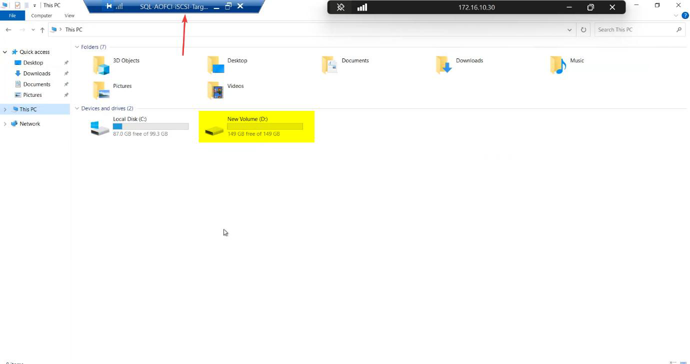
The iSCSI-Target VM needs a backing disk to carve into LUNs. Add a 150 GB virtual disk on a SCSI controller (lab sizing — your production needs scale to your workload + retention).
Step 2 — create the three vSwitches
Open Hyper-V Manager → Virtual Switch Manager. You’ll already have the Public/Domain external switch. Add two more:
- Storage — Private. Carries iSCSI between the SAN VM and both nodes. Bandwidth-heavy, latency-sensitive.
- Heartbeat — Private. Carries cluster heartbeat ONLY between Node-01 and Node-02.
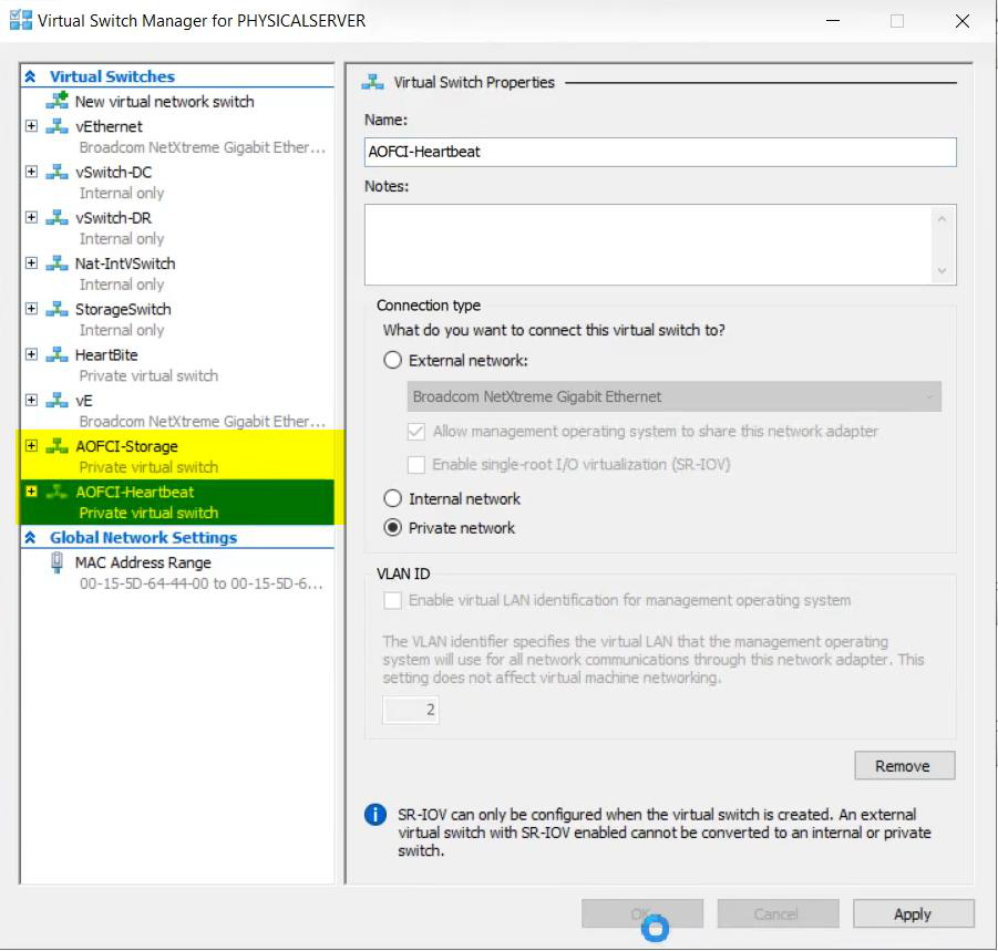
Why Private? Private vSwitches don’t route off-host. Storage stays storage; heartbeat stays heartbeat. Even if the public NIC saturates with backup traffic, the cluster still hears its own heartbeat — no spurious failovers.
Step 3 — configure the storage network
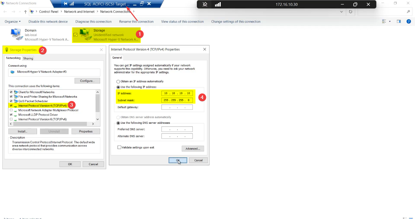
SAN side
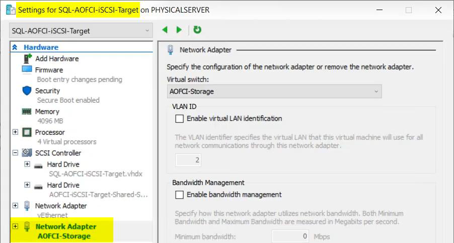
Attach the Storage vSwitch to the iSCSI-Target VM as an additional network adapter.
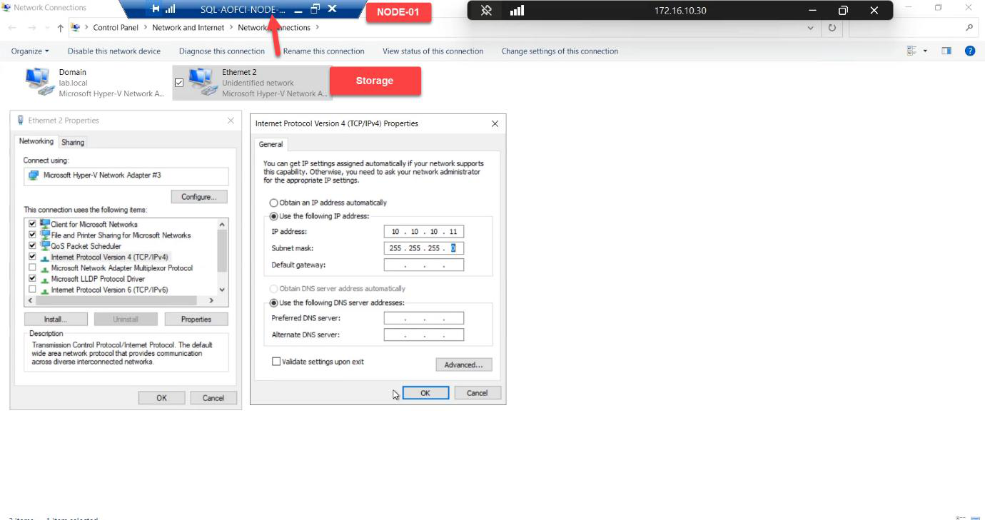
In the guest OS, open Network Connections, find the new adapter, rename it to Storage, set static IP 10.10.10.10 / 255.255.255.0. No default gateway — this is a private subnet.
Storage, IP 10.10.10.10/24, no gateway (private subnet, doesn’t route).Node-01 storage NIC
10.10.10.11/24. Renaming saves you at 03:00.Same pattern: attach Storage vSwitch, rename adapter to Storage, IP 10.10.10.11/24.
Node-02 storage NIC
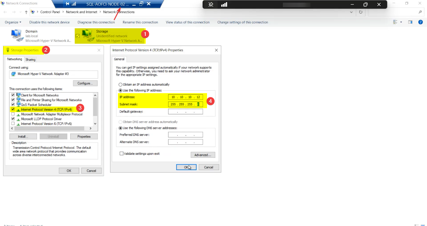
10.10.10.12/24. Symmetry matters — cluster validation barks if NIC names diverge.Mirror Node-01 exactly: Storage adapter, IP 10.10.10.12/24.
Renaming saves your sanity. Default Windows names are Ethernet, Ethernet 2, Ethernet 3 — useless for cluster validation reports and PowerShell scripts. Rename now.
Step 4 — verify storage connectivity (the ping matrix)
Every leg of the storage subnet, every direction. Don’t skip any.
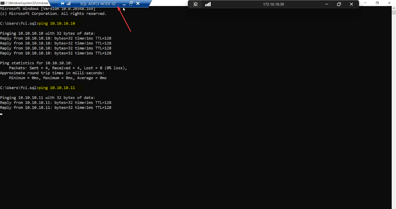
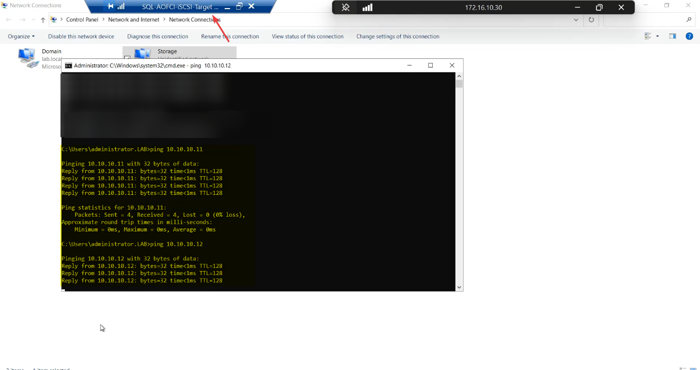
| From | To 10.10.10.10 (SAN) | To 10.10.10.11 (N1) | To 10.10.10.12 (N2) |
|---|---|---|---|
| Node-01 | ✓ | self | ✓ |
| Node-02 | ✓ | ✓ | self |
| iSCSI-Target | self | ✓ | ✓ |
Any cell fails → STOP. Don’t move on. Common causes: Windows Firewall blocking ICMP on the new profile (private profile, ICMPv4 echo request rule), wrong subnet mask, misnamed adapter binding to wrong vSwitch.
Step 5 — configure the heartbeat network
Heartbeat is node-to-node only. The SAN VM does NOT get this vSwitch — the SAN doesn’t vote in cluster quorum, so it doesn’t need to participate in liveness checks.
Node-01 heartbeat NIC
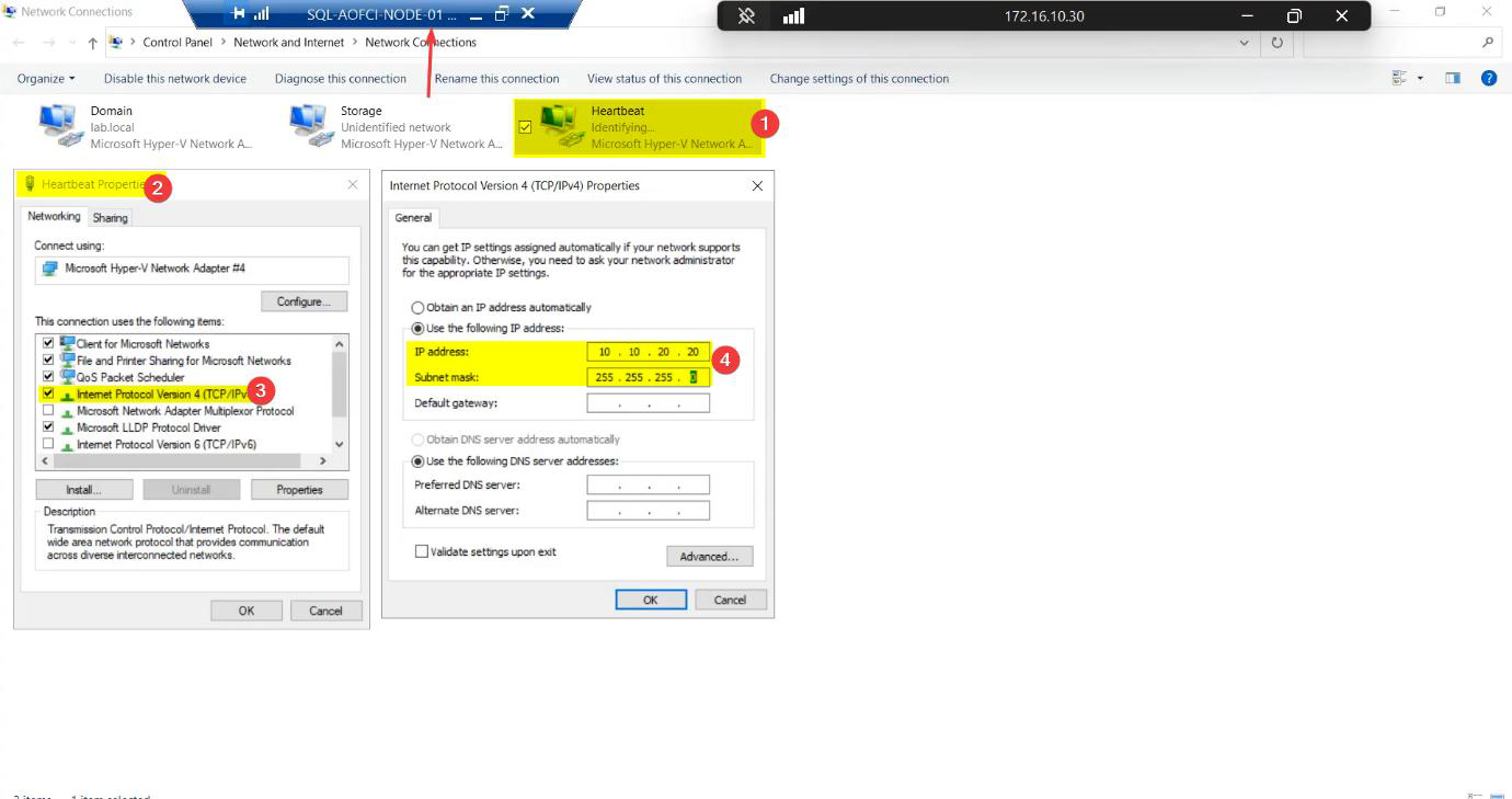
Heartbeat, IP 10.10.20.20/24, no gateway.Attach Heartbeat vSwitch, rename to Heartbeat, IP 10.10.20.20/24, no gateway.
Node-02 heartbeat NIC
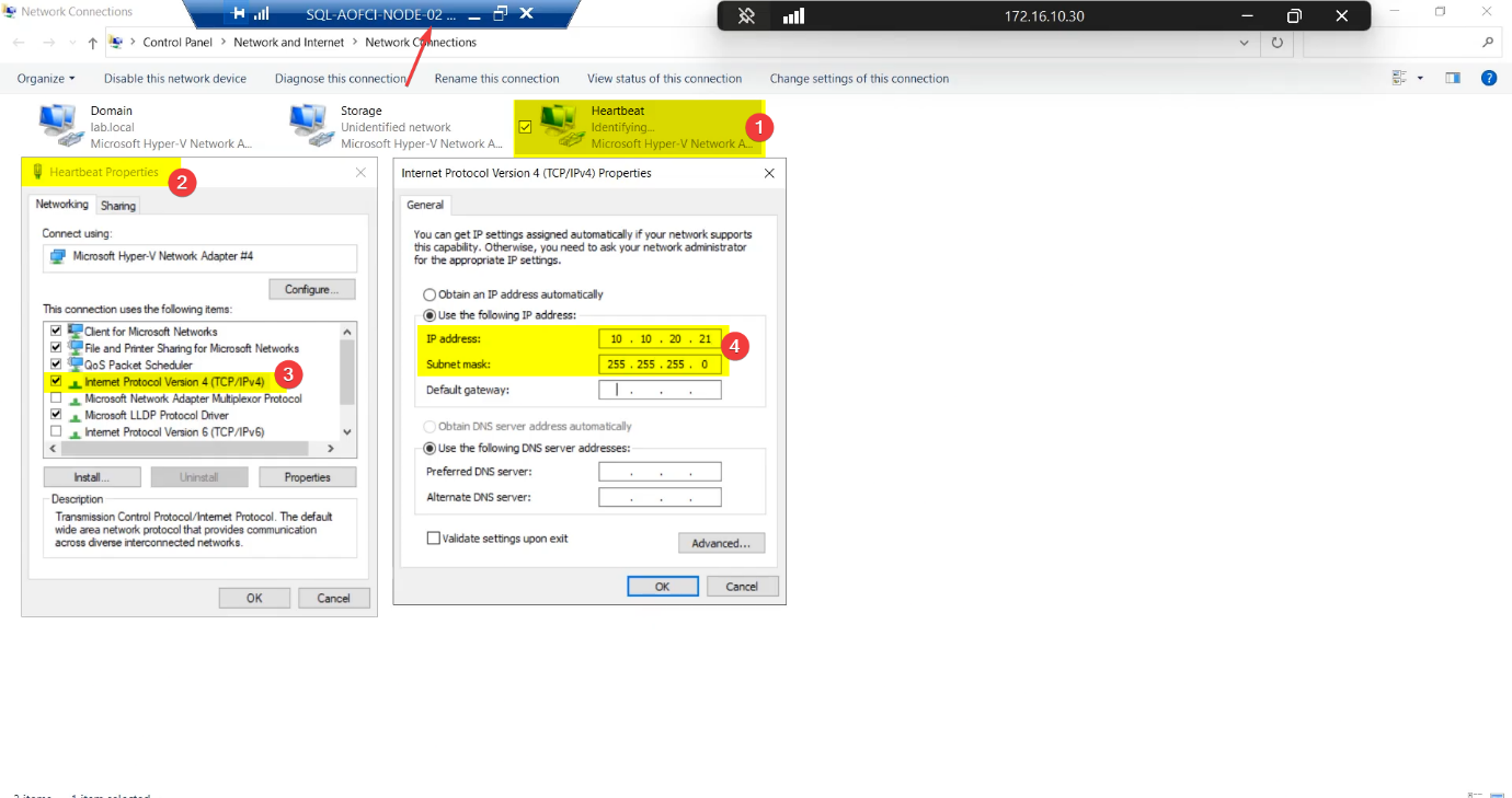
Heartbeat, 10.10.20.21/24. Heartbeat is intentionally private — SAN doesn’t attach.Heartbeat adapter, IP 10.10.20.21/24.
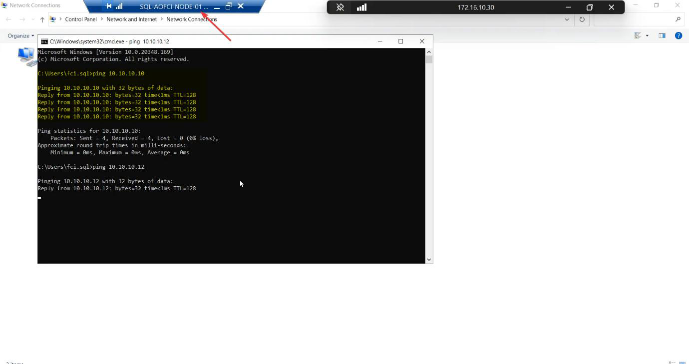
Step 6 — verify heartbeat connectivity
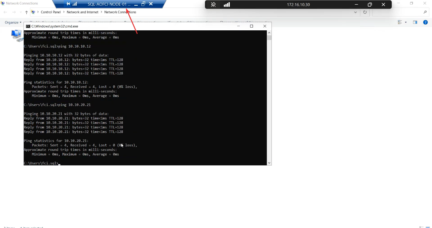
Two pings: N1 → 10.10.20.21 and N2 → 10.10.20.20. Both must succeed.
Things that bite people in this part
Windows Firewall blocks ICMP
Default Windows Server profile blocks inbound echo requests on the “Public” firewall profile. When you put a new NIC on a private subnet, Windows often classifies it as Public and blocks pings. Fix: Set-NetConnectionProfile -InterfaceAlias 'Storage' -NetworkCategory Private and enable the “File and Printer Sharing (Echo Request — ICMPv4-In)” rule for Private.
Adapter binding order
Cluster validation prefers the Public NIC at the top of the binding order. Get-NetIPInterface | Sort-Object InterfaceMetric — lower metric is higher priority. Set Storage and Heartbeat to higher metric than Public.
Renaming after install
If you forget to rename and only do it later, cluster validation flags the NIC name change as a configuration drift. Easier to rename BEFORE adding to the cluster.
Subnet overlap
Cluster Service hates duplicate subnets. Don’t use 10.10.10.x AND 10.10.20.x AND a public 10.10.x.x — the cluster gets confused about which path is which. Keep subnets distinctly separated.
iSCSI Target on the heartbeat network
Don’t attach the Heartbeat vSwitch to the SAN. Doing so puts a non-cluster device into the cluster’s heartbeat conversation and can confuse split-brain detection.
What’s next
Plumbing done. Part 3 configures the iSCSI Target VM as a real SAN — create the iSCSI Target, define the LUNs (Quorum, Data, Log), and set up access permissions for the two cluster nodes. See the full series at SQL Server Clustering pathway.